

Gray Space Bottlenecks: The Engineering Case for Cable Bus in High-Velocity Builds
Artificial Intelligence workloads are decoupling power growth from physical space growth in the modern data center. Legacy facilities once operated comfortably at 5 to 10 kilowatts per rack. The new standard for AI-ready infrastructure pushes toward 40kW, 60kW, and in liquid-cooled configurations, upwards of 100kW per rack. This Density Shock forces a rewriting of the fundamental rules governing facility operation. As power demands climb, the electrical feeder system becomes the critical path for project velocity.
Infrastructure architects now face simultaneous pressure from power source constraints, skilled labor shortages, and a fragile supply chain that is overloading capacity that threatens timely delivery. This Poly-Crisis is reshaping how we specify gray space components. The choice between legacy conduit-and-wire systems and modern cable bus is a major decision about certainty in meeting tight project timelines and energization dates to remain at the leading edge of the AI market.
The Man-Hour Tax on Legacy Feeders
The traditional approach to power distribution by pulling cable through rigid conduit fails under the velocity requirements of 2026 data center builds. The failure mode is primarily economic. Large-scale installations of high-ampacity feeder cables-500 kcmil copper and larger-are physically demanding and slow when handled via traditional approaches. Pulling large-size cable through complex conduit bends requires extra labor resources to ensure cable pulling force does not exceed cable pulling tension limits, and to prevent cable jamming or insulation damage.
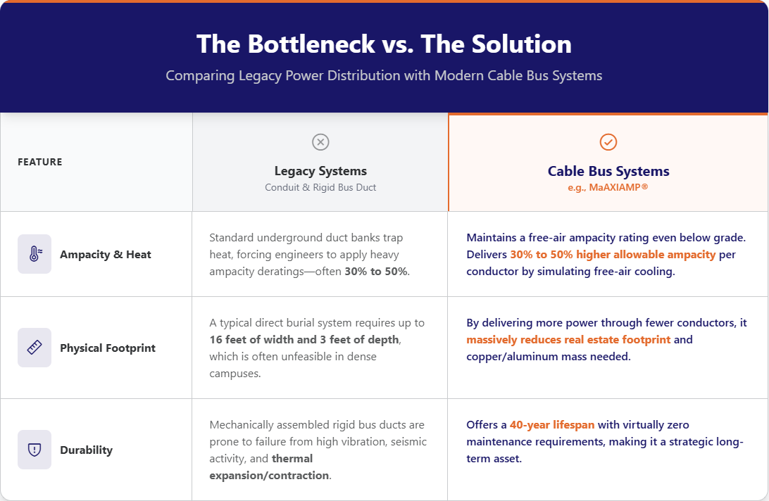
Skilled field labor has become the scarcest resource in the infrastructure supply chain. Every hour an electrician spends on a difficult cable pull is an hour they are not terminating switchgear or commissioning UPS systems. Legacy duct banks and conduit systems also demand significant real estate. A typical direct burial conduit system requires up to 16 feet of width and at least 3 feet of depth below surface to avoid frost line and to maintain proper cable spacing for heat dissipation. In high-density campus environments, this real estate footprint is often technically unfeasible due to existing underground infrastructure such as gas pipeline, water main, sewage drain, etc.
Rigid bus duct systems present their own set of constraints. Lead times for custom bus duct runs frequently exceed 12 weeks. This delay creates a wait state that stalls the entire power-to-market timeline. The mechanically assembled nature of the bus duct also makes it prone to failure in areas of high vibration or seismic activity, ice deposit expansion/contraction during drastic winter when temperature fluctuates. Thermal expansion and contraction remain major causes of breakdown in these systems.
The Physics of Free-Air Ampacity
The primary technical advantage of a cable bus system lies in its ability to maintain a free-air ampacity rating even when installed below grade. Standard underground duct banks trap heat. This requires engineers to apply heavy ampacity deratings-often 30% to 50%-to meet NEC and/or CSA/ANSI code requirements. This inefficiency forces the use of additional expensive power conductors and larger footprints to deliver the same amount of power.
A ventilated underground cable bus system, such as MAXIAMP® Underground system, utilizes proprietary convection venting techniques to remove all the heat generated by the power cable under maximum current load. The system achieves this through a combination of engineered components:
Pre-formed Optimal Cable clamp (Op-Amp): Conductors are secured in a rotating trefoil configuration using one-piece multiloop, non-magnetic aluminum clamps. This arrangement optimizes reduction of the Electromagnetic Field (EMF) generated by the cable bus system. The Op-Amp cable clamps allow air movements in longitudinally along the tray, increasing ventilation effectiveness of the MAXIAMP cable bus. This is a major advantage compared to using block clamps which prevent air movement along the tray.
Ventilation Covers: The aluminum enclosure covers feature rectangular ventilated slots on both top and bottom. These ventilated slot covers promote continuous air flow both vertically and longitudinally. This simulates free-air cooling conditions that standard cable in conduits or other cable bus designs cannot match.
Underground Offset Venting Systems: For below-grade installations, convection heat ventilation technique is used to remove all heat generated from the power cable through the proprietary offset vent system or powered vent system (using motorized fans). These offset vents are designed to eliminate dust/debris from falling directly onto the power cable since the main trench is covered with solid concrete lids. The offset vents also prevent rodent access to the cable bus by using a mesh screen, while allowing the heat to escape.
These physical attributes result in a 30% to 50% higher allowable ampacity per conductor compared to concrete-encased duct systems. By delivering more power through fewer conductors, engineers can reduce the real estate footprint of the power feeder system, saving significant cost through reduction of cable.
Labor Efficiency and Speed to Power
From a project management perspective, the cable bus represents a shift from field-based improvisation to factory-engineered certainty. A system like MAXIAMP arrives as a complete, pre-designed package. It includes technically selected power cables, the ventilated enclosure, entry fittings, bends, and pre-drilled weatherproof entrance plates with installed cable glands, electrical entry layout drawings, trench layout drawings, and installation instructions for tray and trench systems.
This lug-to-lug solution streamlines the technical design, materials, and installation workflow. The enclosure design is based on ladder-type cable tray construction, which most electrical installers already understand. Short-span cable rungs, spaced one foot apart, allow for long cable pulls without the need for specialized cable rollers.
The superior Op-Amps clamping system further accelerates the timeline. Self-centering wing nuts and spring-loaded holding bolts allow installers to secure cables in seconds. Eliminating tools around the cables also reduces the risk of damaging the insulation-a common cause of ground faults due to insulation damage during installation in field-terminated systems.
The effect on the schedule is quantifiable. While bus duct lead times often reach 20-30 weeks, a cable bus system can be manufactured and delivered in as little as 8-12 weeks. This reduction in lead time, combined with the decreased man-hours required for installation, directly addresses the construction velocity bottleneck.
Regulatory Alignment: CSA/ANSI C22.2 No. 273 and NEC Compliance
Credibility in the gray space is built on compliance with established standards. The MAXIAMP system is a cable bus solution certified to CSA/ANSI C22.2 No. 273:19 for use in both Canada and the USA (NEC compliance). This certification ensures that the enclosure, conductor sizing, and terminations have been tested as a unified cable bus system to withstand the short-circuit rating up to 100kA RMS for 10 cycles.
Specifications should also reference NEC 370, clause 370.80 “Ampacity of Conductors” regarding free-air rating cable ampacity for cable bus. While NEC Table 310.16 addresses non-free air ampacities, a certified cable bus allows engineers to reference Table 310.17 for free-air ratings for cable voltage of 2000V or less. For voltages from 2001V to 35,000V, engineers can refer to NEC Table 315.60(C)(3) for copper and 315.60(C)(4) aluminum conductors. This major shift in the regulatory framework enables the massive reduction in copper/aluminum mass and the physical footprint.
The Forward Look: Infrastructure in 2026
As we move into the 2026-2027 infrastructure planning cycle, the focus will shift from simple capacity to modularized feeder infrastructure. The insatiable demand for AI clusters will continue to stress utility interconnection timelines or onsite power generation. Facilities will be forced to densify power distribution within fixed footprints.
The legacy approach of pulling individual conductors through miles of conduit is reaching its thermal and economic limit. The transition to engineered cable bus systems is a logical and economical step toward project certainty. These systems offer a 40-year lifespan with virtually zero maintenance requirements. This makes them a strategic asset for the owner and for the long-term operational health of the facility.
Infrastructure architects must now decide if they will continue to pay the man-hour tax or if they will adopt pre-engineered solutions that manufacture time. The physics of AI workloads leave little room for the inefficiencies of the past.

GCG Data Center Solutions
Jeff Young, Director of Strategic Accounts, GCG Data Center Solutions
Jeff Young is Director of Strategic Accounts at GCG Data Center Solutions, where he works with hyperscale operators, colocation providers, and enterprise clients on power distribution infrastructure for high-density deployments. With over 25 years in data center infrastructure, Jeff specializes in the electrical and thermal challenges of AI/ML workloads.